Skip to main content
Key takeaways:
- The Windows Driver Model (WDM) provides a kernel-mode framework for creating drivers that manage hardware or virtual devices and handle low-level system tasks.
- With a WDM driver, you can implement encryption logic, performance optimizations, integration with other system components, and more.
- Developing a WDM driver requires tools like Visual Studio, Windows SDK, and WDK, along with careful adherence to kernel-safe coding practices.
- Best practices for custom driver development include registering unload routines, ensuring compatibility with different Windows versions, and implementing security measures such as data encryption.
Windows drivers sit at the core of many high-performance and security-critical products, from storage solutions and cybersecurity tools to virtualization platforms and enterprise hardware. To securely and efficiently work with user data, such applications rely on software drivers that process user-mode requests and return results to the application.
Building a reliable kernel-mode driver requires specialized expertise both in driver development and the Windows ecosystem. In this article, we walk you through each step of development, from designing the Windows driver architecture to debugging.
Whether you’re evaluating custom driver development for your product or looking for a partner with proven experience, this guide will give you a clear view of what driver development involves and what high-quality engineering looks like in practice.
This article will be useful for development teams and project leaders who are getting into driver development or are looking for ways to improve and maintain their legacy Windows drivers.
Contents:
- Developing a WDM driver: First steps
- Encryption disk architecture
- Building a WDM driver
- Creating a device object
- Registering callback methods
- Implementing callback methods
- Implementing read/write operations for a virtual disk
- Mounting the disk
- Unmounting the disk
- Encrypting the disk
- Running a demo
- Finalizing the implementation of WDM requirements
- Debugging the disk
- How Apriorit helps you build custom drivers
- Conclusion
Developing a WDM driver: First steps
In this article, we’ll show you how to write a driver for Windows that creates an encrypted virtual disk — a file that operates similarly to a physical disk. The driver’s key task will be to process requests received from the operating system and send them to the virtual disk instead of a real device.
Our driver won’t directly interact with any physical devices or hardware. You’ll be able to see the virtual disk in File Explorer and use it to create, save, and delete data. The driver will be written in C, so we’ll also cover some language-related limitations.
To follow along with our driver development guide, you’ll need the following tools:
- Visual Studio. We used Visual Studio 2019. To develop drivers for Windows 11, you can use Visual Studio 2022.
- Windows Software Development Kit (SDK) for versions older than Visual Studio 2017; we used SDK version 10.0.19041.0.
- Windows Driver Kit (WDK). We used WDK version 10.0.19041.685. To develop drivers for Windows 11, use WDK version 10.0.22621 or later.
- VMWare
Note: Starting with Visual Studio 2017, Windows SDK is installed automatically when you select the Desktop development with C++ option when installing Visual Studio. Windows driver development kit, however, still must be installed separately.
If WDK was installed properly, you’ll see driver project templates in the dialog window for creating new Visual Studio projects:
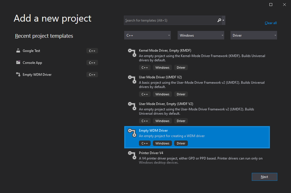
Screenshot 1: Visual Studio 2019 interface for creating driver projects
Working with WDK
Note that your approach to working with WDK depends on the version(s) of Windows you want your driver to be compatible with.
Before Visual Studio 2012 (WDK 8.0), Windows Driver Kit was a standalone solution that had its own compiler and other tools needed for developing a Windows driver. Driver assembly used to consist of two main steps:
- Call the setenv.bat script to set build options
- Call the build.exe utility from WDK
To build a basic driver for Windows, you needed two files:
1. The Makefile file, containing a directive to include the final makefile from the WDK. This directive was always standard:
!include $(NTMAKEENV)\makefile.def2. The Sources file, containing build options and a list of driver sources.
WDK is currently integrated into Visual Studio via an extension that gets installed automatically. Therefore, you no longer need to work with Sources and Makefile, as you can select the project type, WDK version, and libraries to link to your driver in project settings.
When you use older versions of WDK to build drivers supporting Windows OS, your driver should also be able to support newer versions of Windows. However, to enable support for older Windows versions, you might need to use older versions of WDK when building your driver.
For example, to build a driver supporting Windows XP, you’ll need to use WDK version 7.1.0 (7600.16385.1) or older. This driver will also work under Windows versions 7, 8, 10, and 11. At the same time, with WDK version 10.0.19041.685 (used in our guide), you can build a driver that supports Windows 7 or later, but it won’t work properly on Windows XP.
To learn more about writing drivers for different Windows versions, read Microsoft’s recommendations.
Overall, if you’re working on a new driver that doesn’t need to support older versions of Windows, it’s best to use the latest WDK version and create the project directly in Visual Studio.
With that in mind, let’s move to the actual process of Windows driver development.
Need help with complex Windows driver tasks?
Rely on our seasoned engineers to test, bug-fix, certify, and maintain robust Windows drivers tailored to your product’s performance and security needs.
Preparing to develop a Windows driver
Microsoft explains in detail the nature and purpose of drivers in Windows. Below, we summarize the core information you need to know to follow our guide.
First, let’s outline what a driver is and what its tasks are. A driver is a portable executable (PE) file that has a .sys extension. The format of this file is similar to the format of any .exe file, but the driver file links to the kernel (ntoskrnl.exe) and other system drivers (although this capability won’t be used in our example):
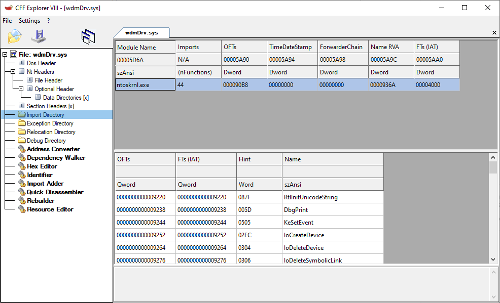
Screenshot 2: List of a driver’s linked modules with imported APIs
Drivers also have a different entry point — the GsDriverEntry function and the /SUBSYSTEM – NATIVE parameter.
Usually, drivers are written in C. However, as Microsoft doesn’t provide things like a C runtime for the kernel or a standard C++ library, you can’t use common C++ features like new/delete, C++ exceptions, or global class object initialization in the kernel. You can still write your code in a .cpp file and state a class, and the compiler will understand it; but full-scale support for C++ is absent.
Also, Microsoft recommends not using standard C++ functions like memcpy and strcpy for kernel driver development, even though they can be exported by the kernel. Instead, they recommend using safe implementations designed specifically for the kernel, such as the RtlCopyMemory and RtlCopyString functions.
To work with a project that relies on C, you can use a C++ runtime (cppLib) and an STL library (STLport) ported to the kernel. To simplify our example, we don’t use either of those and work with almost pure C.
To make it easier to write drivers, Microsoft created the Windows Driver Framework (WDF). This framework can help you significantly shorten the code for interacting with Plug and Play (PnP) devices and power management.
WDF is based on the Windows Driver Model. The choice of a driver model depends on many factors, including the type of driver under development.
With WDF being more suitable for building device drivers, in this article, we build our software driver with WDM.
Encryption disk architecture
To build properly functioning WDM drivers, we need to create two components:
- wdmDrv.sys — a driver that implements a virtual disk in Windows
- wdmDrvTest.exe — a user application that manages the driver
First, we need to mount our disk so it appears in the system and is accessible from File Explorer. To do this, we need a separate user application — wdmDrvTest.exe — that will send commands to the driver to mount and unmount the disk. We can also use the Windows registry to specify mount options for the disk (disk letter, path to the virtual disk file, disk size, etc.) and read those options when the driver is loaded into the system.
Then, for reasons of data security, we need to make sure the data is encrypted before it’s written to the disk and decrypted only after it’s read from the disk. As a result, data stored on the disk will always be encrypted.
Our driver is responsible for performing read/write operations on our virtual disk. The WdmDrvTest.exe application is responsible for encrypting and decrypting data. This application can also read and write data to and from the file where our virtual disk is stored. Therefore, our driver will delegate the processing of read/write operations to wdmDrvTest.exe.
Building a WDM driver
Any Windows driver starts with the DriverEntry function, which is called by the Windows operating system when the driver is loaded:
NTSTATUS DriverEntry(
IN PDRIVER_OBJECT DriverObject,
IN PUNICODE_STRING RegistryPath)In our case, this function is responsible for:
- Creating a device object that will receive control commands.
- Registering callback methods that Windows calls for the created device objects. For example, in the case of a request to read data from the disk, the system will call a read callback in our driver.
- Registering the DriverUnload method, which Windows calls to unload the driver and free the allocated resources.
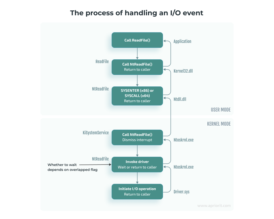
Basically, the DriverEntry function works similarly to the Main function in user applications.
However, while the Main function executes a certain algorithm and then returns control to the operating system, a driver remains loaded in memory and waits for Windows to call the appropriate handler in response to a new event even after execution of the DriverEntry function.
The following diagram shows the execution of a process in user mode and the work of a driver as part of a system process:
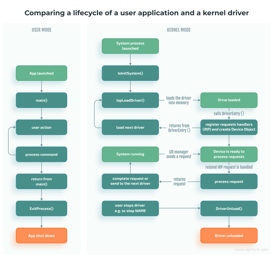
Here, the input/output (I/O) manager should be seen as a set of functions called to process I/O events rather than a separate module in the system.
Creating a device object
To create a device object, use the IoCreateDevice and IoCreateDeviceSecure functions:
NTSTATUS IoCreateDeviceSecure(
    [in]             PDRIVER_OBJECT     DriverObject,
    [in]             ULONG              DeviceExtensionSize,
    [in, optional]   PUNICODE_STRING    DeviceName,
    [in]             DEVICE_TYPE        DeviceType,
    [in]             ULONG              DeviceCharacteristics,
    [in]             BOOLEAN            Exclusive,
    [in]             PCUNICODE_STRING   DefaultSDDLString,
    [in, optional]   LPCGUID            DeviceClassGuid,
    [out]            PDEVICE_OBJECT     *DeviceObject
);
IoCreateDeviceSecure allows us to additionally specify the parameters for the DefaultSDDLString security descriptor. For example, we can specify which user groups can write to the device. Starting from Windows 7, this parameter must be used to, for instance, successfully format a disk.
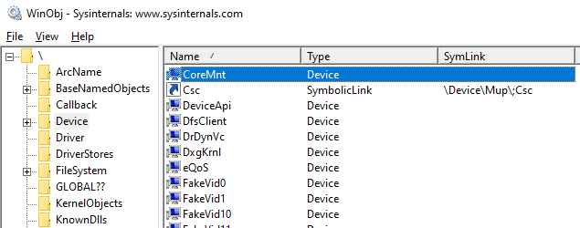
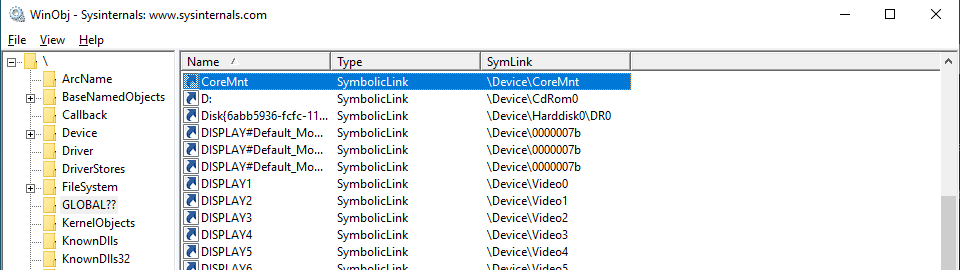
The DeviceName parameter is the name of the device, which might look like \Device\MyDevice. This parameter is created in the Device directory, which is a standard directory where all devices in the system are listed. To view this directory, we can use the winobj utility. Here is our virtual disk in the Device directory:
However, the devices in this directory can’t be accessed from user mode. Therefore, if we try to open a device by calling the CreateFile function, we’ll get the INVALID_HANDLE_VALUE value with the ERROR_FILE_NOT_FOUND error.
To make a device accessible from user mode, we need to create a symbolic link to it in the GLOBAL?? directory. To do that in the kernel, we call the IoCreateSymbolicLink function:
Now, using the name of our device, any user application can open the device object and send requests to it:
CreateFileW(L"\\.\CoreMnt", GENERIC_READ | GENERIC_WRITE, 0, NULL, OPEN_EXISTING, 0, NULL);To learn more on the topic of naming device objects, you can read the guidelines from Microsoft or the Naming Devices section in the book Programming the Microsoft Windows Driver Model by Wolter Oney.
Continuing with our guide, we need to create two devices:
- A control device for interacting with the user application: particularly, for performing mount/unmount commands on our disk. This device is created in DriverEntry.
- A disk device for receiving and processing I/O operations. The control device creates a disk device when it receives the disk mount command.
Now, let’s look closer at the rest of the IoCreateDeviceSecure parameters:
DriverObject is a structure created by Windows and passed to the DriverEntry function. This structure contains a list of all device objects created for the driver.
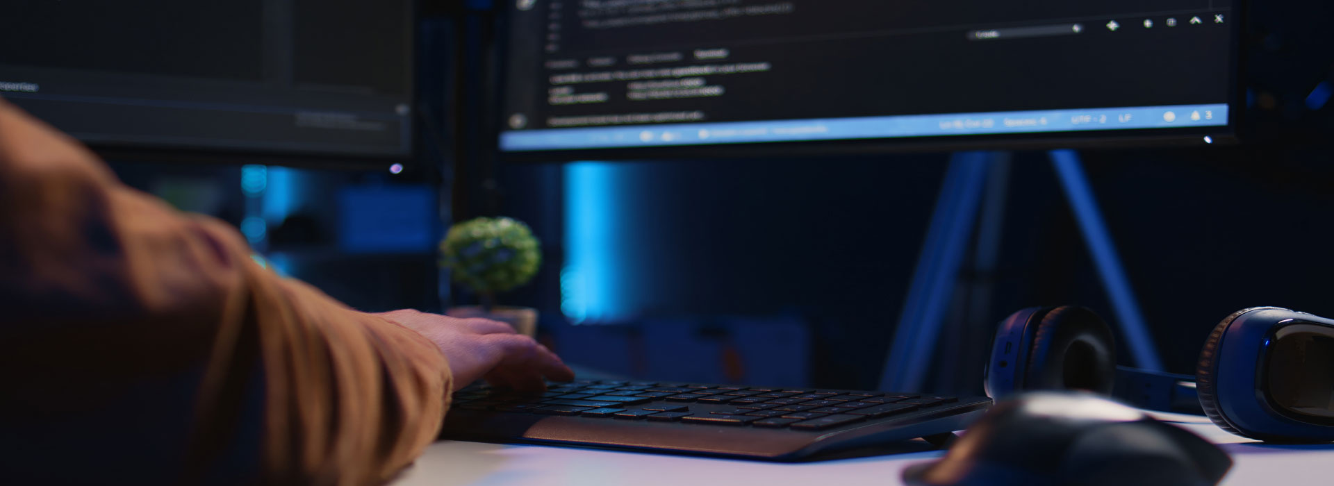
Here’s how we can find a DriverObject by the driver name and see the entire structure using WinDbg (see the Debugging the disk section below) and the !drvobj command:
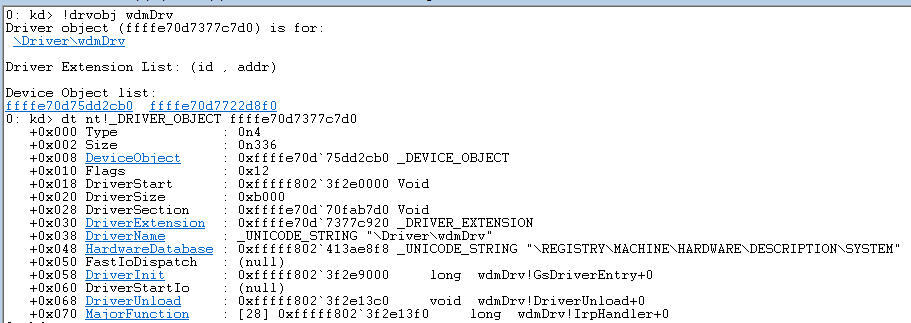
DeviceExtensionSize is the parameter defining the size of the structure that we want to store in the created device object. This parameter is specified in the DeviceExtension field.
Windows will allocate memory for this structure and save the pointer to it in the created device object. This structure is where we will store everything we need to process requests: the I/O request queue, disk size, etc. In terms of C++ classes, this structure can be seen as the device object’s data members.
DeviceType is one of the numerical values defined in wdm.h, such as FILE_DEVICE_DISK, FILE_DEVICE_PRINTER, and FILE_DEVICE_UNKNOWN. Based on this parameter, the system assigns a default security descriptor to the device object of the virtual disk.
DeviceCharacteristics defines additional device characteristics such as FILE_READ_ONLY_DEVICE. In our case, we pass 0 as the value of this parameter.
Exclusive is a parameter that prohibits the opening of more than one device handler (HANDLE). In our case, we set the value of this parameter to FALSE.
DeviceObject is the address of the created device object.
The next important step in writing WDM drivers is registering its callback methods. Let’s take a look at this process.
Read also
WHQL Driver Testing & Hardware Certification by Microsoft: Step-by-Step Process
Explore what goes into successful HLK testing and WHQL certification, from tooling and validation to common issues teams encounter. Get insights that will help you pass certification without hurdles.

Registering callback methods
Windows uses the I/O request packet (IRP) structure to handle various I/O events. For solutions where we have two different drivers interacting with each other, we can create and send IRPs to the second driver ourselves. But in our case, the operating system is responsible for both creating this structure and passing it to the driver.
Let’s see how an I/O event is usually handled, using the ReadFile function as an example. When the ReadFile function is called, this is what happens in the user application:
1. The ReadFile function calls the ntdll!NtReadFile function, which switches to kernel mode and calls the corresponding nt!NtReadFile function in the kernel (ntoskrnl.exe).
2. Using the passed HANDLE for the nt!NtReadFile file, the nt!NtReadFile function:
- Finds the device corresponding to the file. For example, this can be done through calls to ObReferenceObjectByHandle or IoGetRelatedDeviceObject functions.
- Creates an IRP structure using, for example, a call to the IoAllocateIrp function.
- Calls the appropriate device driver by passing the created IRP structure to it. This can be done by, for example, calling the nt!IoCallDriver function.
Note that the HANDLE is stored in the table of process objects and therefore only exists within a specific process.
3. The nt!IoCallDriver function takes a pointer to the driver object from the structure describing the device and passes the received IRP structure to the appropriate handler. The pseudocode for this process looks like this:
NTSTATUS IoCallDriver(PDEVICE_OBJECT device, PIRP irp)

{

// get FunctionIdx from irp

PDRIVER_OBJECT driver = device->DriverObject;

return(*driver->MajorFunction[FunctionIdx])(device, irp);

}4. The execution flow is then transferred to the IRP_MJ_READ (0x03) handler of the corresponding driver.
Note that there’s a function similar to NtReadFile — the ZwReadFile function. ZwReadFile can be exported by both the kernel and ntdll. If we need to call a function from the user mode, we can work with either NtReadFile or ZwReadFile. But if we need to call a function from the kernel mode, then it’s best to use ZwReadFile, as it allows us to avoid errors when passing the data buffer from the user mode. You can learn more about working with these two functions in Microsoft documentation.
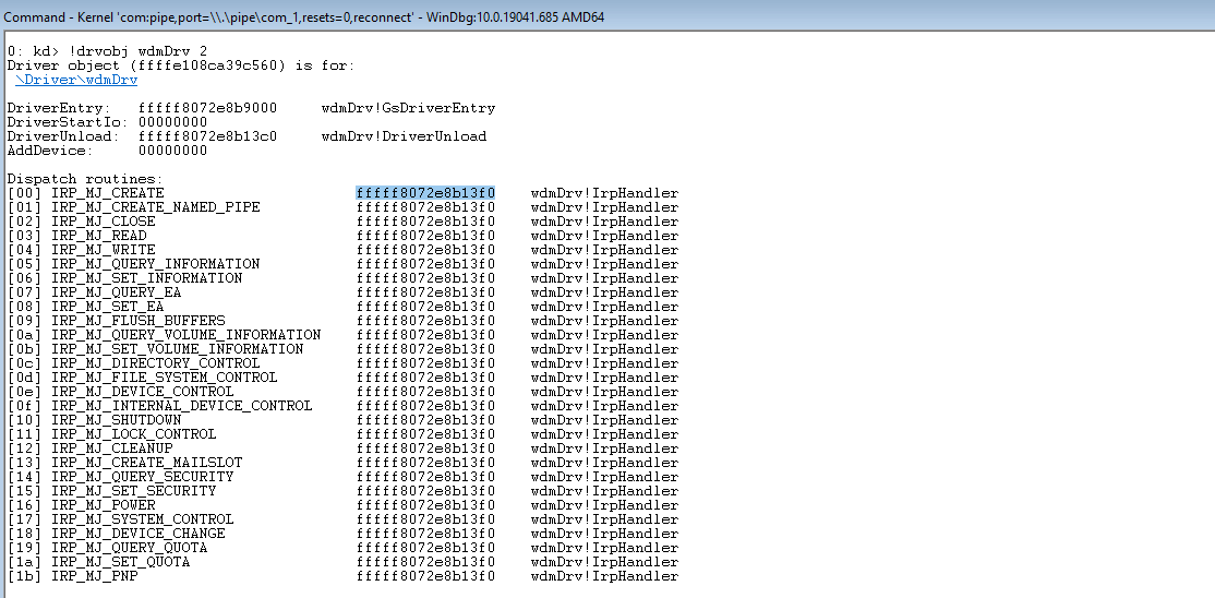
To process various control events or I/O events, the driver needs to register the appropriate handlers in the DriverObject->MajorFunction array. The full list of supported functions can be found in the wdm.h file.
For example, to process read/write requests, we need to provide implementations of functions with the IRP_MJ_READ and IRP_MJ_WRITE indexes:
NTSTATUS IrpHandler(IN PDEVICE_OBJECT fdo, IN PIRP pIrp){...}

NTSTATUS DriverEntry(IN PDRIVER_OBJECT DriverObject, ...)

{

DriverObject->MajorFunction[IRP_MJ_READ] = IrpHandler;

DriverObject->MajorFunction[IRP_MJ_WRITE] = IrpHandler;

}However, we don’t have to register all possible handlers. The system provides a default implementation that reports failed request processing. We can also see all handlers registered for a particular driver:
Note: It’s impossible to unload a driver without registering the DriverUnload method. Antivirus software and similar products often leverage this feature to ensure that no one can unload their drivers from the system.
Read also
How to Use WinDbg for Kernel Debugging to Develop a Reliable Windows Driver
Optimize your debugging workflow by learning to use WinDbg from a real-life example. Discover best practices and tips from our experts.

Implementing callback methods
When creating the IRP structure, the I/O manager allocates an array of IO_STACK_LOCATION structures for it. This array is located at the very end of the IRP structure.
The array size is specified in the DEVICE_OBJECT structure of the device that will receive this IRP first; specifically, in the StackSize field of this structure. The MajorFunction code is also located in this structure and not in the IRP itself. As a result, the operation code may change when the IRP structure is passed from one device to another. For example, when passing a request to read to a USB device, the operation code may change from IRP_MJ_READ to something like IRP_MJ_INTERNAL_DEVICE_CONTROL.
To access the IO_STACK_LOCATION structure of the current device, we need to call the IoGetCurrentIrpStackLocation function. Then, depending on the value of MajorFunction, we need to perform the corresponding operation:
PIO_STACK_LOCATION ioStack = IoGetCurrentIrpStackLocation(irp);

switch(ioStack->MajorFunction)

{

caseIRP_MJ_CREATE:

...

caseIRP_MJ_WRITE:

...

default:

returnCompleteIrp(irp, STATUS_INVALID_DEVICE_REQUEST, 0);Overall, there are three possible scenarios for request processing:
1. Process the IRP request immediately. For example, if it’s a request for disk size (IOCTL_DISK_GET_LENGTH_INFO), we can return the result immediately, as this information is known:
irp->IoStatus.Status = STATUS_SUCCESS;

irp->IoStatus.Information = 0x1000000;

IoCompleteRequest(irp, IO_NO_INCREMENT);

returnSTATUS_SUCCESS;In case of failed request processing, the Information field usually has a 0 value in it. If a request is processed successfully, this field will contain the size of the data to be sent.
The IO_NO_INCREMENT (0) value means there’s no need to boost the priority of the threads waiting for IRP completion. If we were building a sound card driver, we could pass the IO_SOUND_INCREMENT (8) value, where 8 would represent the priority level corresponding to the driver type.
2. Pass the IRP request to the next driver in the device stack. While we don’t do this in our example, it can be done with the following command:
IoSkipCurrentIrpStackLocation(irp);

returnIoCallDriver(lowerDeviceObject, irp);This scenario can be used, for instance, when we need to process requests in a minifilter driver.
3. Save the IRP request to be further processed by the driver and mark it as pending. Add this structure to the list stored in the device’s extension and return STATUS_PENDING (see the example below). This scenario is often applied for read/write operations and can be used when, for example, there’s a call to a real device that needs to be processed after processing the initial request:
IoMarkIrpPending(irp);

ExInterlockedInsertTailList(list, &irp->Tail.Overlay.ListEntry, listLock);

KeSetEvent(&requestEvent, (KPRIORITY)0, FALSE);

returnSTATUS_PENDING;Next, in the case of a synchronous call, the user mode application that called the Read/WriteFile function will call NtWaitForSingleObject for the HANDLE file to wait for the operation’s completion. Later, our driver will complete the stored IRP request by calling the IoCompleteRequest function. Calling this function will cause the event inside nt!_FILE_OBJECT to be set, which, in turn, will end the waiting for the HANDLE file.
Here’s how you can put a breakpoint in the code above to see the IRP request:
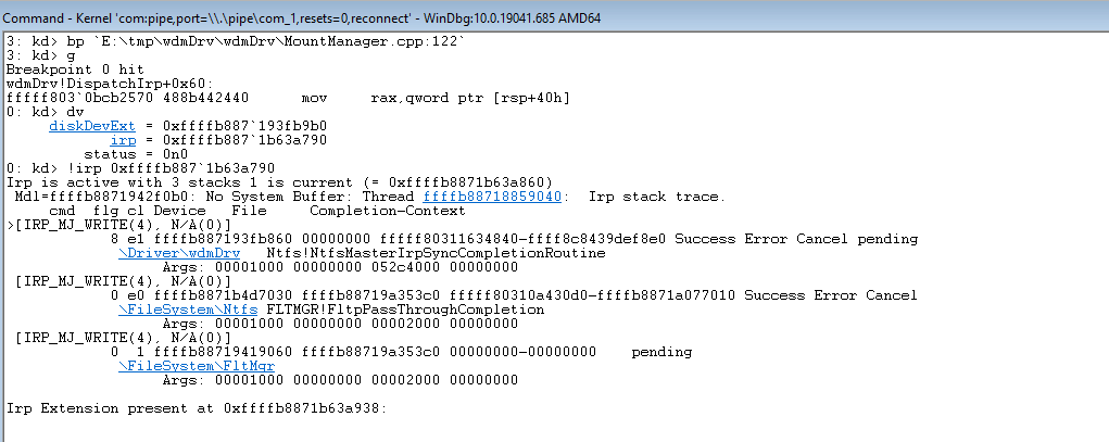
Now, let’s move to implementing read/write operations for a virtual disk.
Read also
How to Develop a Windows File System Minifilter Driver: Complete Tutorial
Elevate your Windows security with custom minifilter drivers. Discover the step-by-step development process and safeguard your system today.
Implementing read/write operations for a virtual disk
As we mentioned earlier, read/write requests are saved to a list stored in the device extension. Here’s a common way to process such requests:
- Create a thread in the kernel where we subtract requests from this list in a loop.
- Execute the corresponding operation of reading or writing to the file.
- For read operations, copy read data to the irp->MdlAddress buffer.
- Complete the request by calling the IoCompleteRequest function.
With this approach, requests are fully processed within the driver. However, as we need to work with the virtual disk file on the user application’s side, we need to apply a different approach where:
- The wdmDrvTest.exe application creates a thread in which it requests data on the last saved request from the driver.
- Based on the data received after Step 1, wdmDrvTest.exe reads data from and writes data to the disk file.
- The application sends the result back to the driver.
- In the case of a read operation, the driver copies the read data to IRP.
- The driver completes the request by calling the IoCompleteRequest function.
When compared to processing requests directly in the driver, this approach has several advantages. It enables us to:
- Use various libraries available in user mode
- Use programming languages other than C/C++
- Place the logic in DLLs, which we can dynamically load or replace without unloading the entire driver or rebooting the system
- Simplify code testing
- Increase overall system stability, as even if an error occurs, it doesn’t lead to a system shutdown.
However, this approach also has disadvantages — the increased complexity of and time needed for request processing.
Let’s see how this approach works in practice.
To request the saved IRP, we need to send a special control code (ioctl) from the wdmDrvTest.exe application. To do this, we call the DeviceIoControl function so the driver receives the IRP_MJ_DEVICE_CONTROL request.
First, we wait for the setting of the event, indicating that the request has been added to the list (see the previous section). Then we get the object of the saved IRP.
KeWaitForSingleObject(requestEvent, Executive, KernelMode, FALSE, NULL);

PLIST_ENTRY request;

if((request = ExInterlockedRemoveHeadList(list, listLock)) == NULL)

{

// the list is empty, the event is set during unmounting

returnSTATUS_SUCCESS;

}

PIRP lastIrp = CONTAINING_RECORD(request, IRP, Tail.Overlay.ListEntry);From the IRP, we get data such as the offset on the disk for read/write operations, the size of the data, and the data buffer for write operations. Then we copy this data to irp->AssociatedIrp.SystemBuffer and complete the IRP_MJ_DEVICE_CONTROL request. After that, we can perform steps two through five.
Working with the lpOverlapped parameter
When implementing read/write operations, it’s crucial to properly configure the lpOverlapped parameter when calling the DeviceIoControl function.
lpOverlapped is a pointer to the OVERLAPPED structure for making asynchronous calls. If you don’t pass this parameter to the DeviceIoControl function, the call to this function will be executed synchronously, which may cause wdmDrvTest to hang when sending other ioctl calls.
Here is what can happen when this disk unmounting scenario takes place:
- Thread 1 sends an ioctl call to get a saved request.
- The driver receives this ioctl call and waits for a new request to appear in the request list.
- Thread 0 (main) tries to send an ioctl call to unmount the drive.
- Thread 0 hangs because the DeviceIoControl function is waiting for the call from step 2 to be completed.
Now, we can move to the process of disk mounting.
Mounting the disk
Onсe we’ve created a disk device and implemented IRP processing for it, we need to make this device available for users so that it can be accessed from File Explorer. To do this, we need to create a symbolic link between our disk device and the drive name:
UNICODE_STRING deviceName, symLink;

RtlInitUnicodeString(&deviceName, L"\\Device\\CoreMntDevDir\\disk");

RtlInitUnicodeString(&symLink, L"\\GLOBAL??\\Z:");

NTSTATUS ntStatus = IoCreateSymbolicLink(&symLink, &deviceName);We need to create such a symbolic link in the global namespace so that the Z drive can be:
- Seen from the wdmDrvTest.exe application launched in administrator mode so we can lock the volume before unmounting (see the next section)
- Found via File Explorer and launched by a regular user
After that, the first time a file or folder is accessed on the drive, the I/O manager will mount the volume:
05 nt!IopMountVolume

06 nt!IopCheckVpbMounted

07 nt!IopParseDevice

08 nt!ObpLookupObjectName

09 nt!ObOpenObjectByNameEx

0a nt!IopCreateFile

0b nt!NtCreateFile

0c nt!KiSystemServiceCopyEnd

0d ntdll!NtCreateFile

0e KERNELBASE!CreateFileInternal

0f KERNELBASE!CreateFileWDuring volume mounting, the system creates a volume parameter block (VPB) and links the volume device object (also created by the system) to the device object of our drive. The VPB address will be saved to the VPB field inside our device object.
Here’s what it looks like for our disk:
Unmounting the disk
While the system automatically creates a device object for the volume and associates it with our disk through the VPB structure, unmounting this volume is still our task.
The whole process consists of the following steps:
- Unmount the volume
- Complete the thread that receives requests from the driver
- Delete our disk device object by calling the IoDeleteDevice function
- Delete the symbolic link to the Z drive
Note: Volume unmounting should always be performed first because the system can write data from the cache to the disk even during unmounting, potentially causing the system to hang.
The logic of the volume unmounting process is implemented in the wdmDrvTest.exe application. The application sends the following ioctl requests to the volume: FSCTL_LOCK_VOLUME, FSCTL_DISMOUNT_VOLUME, and FSCTL_UNLOCK_VOLUME. These commands can only be run by a user with administrator rights.
After executing these commands, the VPB in our Device Object will be updated and will no longer contain a pointer to the volume device object.
At this point, we only have one control device object left for our driver. We can resend a disk mounting request to this device object, thus causing the whole cycle to repeat itself. This control device object will be removed after calling the DriverUnload function and unloading our driver.
Now, let’s talk about the security of our disk’s data.
Encrypting the disk
To secure the disk, we can use OpenSSL to implement data encryption in our wdmDrvTest.exe application.
Here’s what the encryption algorithm would look like when our user application receives a read request from the driver:
1) The application reads the data from the file with the contents of our virtual disk (see screenshot 10 below)
2) The application deciphers the requested data
3) The application returns the deciphered results to the driver so that the driver can copy that data to the IRP request and complete it
void EncryptedImage::Read(char* buf, uint64_t offset, uint32_t bytesCount)
{
    if (bytesCount % SECTOR_SIZE || offset % SECTOR_SIZE)
    {
        throw std::exception("wrong alignment");
    }
    std::vector<unsigned char=""> encData(bytesCount);
    m_image->Read(&encData[0], offset, bytesCount);

    uint64_t startSector = offset / SECTOR_SIZE;
    DecryptLongBuf(encData, bytesCount, startSector, m_key, buf);
}In the case of a write request, the algorithm would be a bit different — we would first need to encrypt the data, then write it to the disk.
When we mount the disk in the wdmDrvTest.exe application, the system passes a password to the PKCS5_PBKDF2_HMAC function. We get the encryption key from that password.
The size of our encryption key is 256 bits, but since it’s encoded with the 128-bit Advanced Encryption Standard (AES) ciphertext stealing (XTS) cipher, the key gets split into two blocks of 128 bits each. The first block will be used for encrypting the data, and the second block will be used for encrypting the tweak.
A tweak is basically an analog of the initialization vector in Cipher Block Chaining (CBC). The only difference is that a tweak is applied for each block — not only the first one. The tweak is generated from the disk sector number, so different tweaks will be used to encrypt different sectors of our disk.
There are two key advantages of working with this cipher:
1) Each data block (disk sector) is encrypted independently from the others
2) For different data blocks, the same plaintext will return different ciphertext
As a result, even if one disk sector gets damaged, decryption of the remaining sectors won’t be affected. In the case of CBC, this would be impossible because each data block relies on the encryption results of the previous block. At the same time, the use of a tweak prevents data leaks common with electronic codebook (ECB) mode, which also encrypts all blocks independently.
It’s also possible to implement encryption directly in the driver using standard tools like Cryptography API: Next Generation and BitLocker. However, these tools support AES-XTS encryption only in Windows 10 and 11.
With most of the technical steps of our driver development processes over, let’s try to run the driver we’ve created.
Running a demo
Once we’ve finished with all the preparations, all that’s left is to click the Build Solution button in Visual Studio to complete the process of building our driver. After that, we can configure a virtual machine running Windows 10 to launch and debug our driver. For our example, we used VMWare.
Note: When setting up a virtual machine in VMWare, it’s important to enable secure boot in the settings:
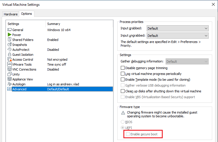
Otherwise, the following commands won’t work.
First, we need to allow the loading of test-signed drivers so that the driver will be automatically signed with the wdmDrv.cer certificate during the build. To do that, we need to run the following command as an administrator:
> bcdedit.exe -set TESTSIGNING ONThen, we need to copy the binaries and run the deploy.bat script (also as an administrator). This script copies our driver to the \system32\drivers\ directory and loads it.
After that, we can run the wdmDrvTest.exe application. The following command creates a vd.img file in the current folder and mounts the disk:
> wdmDrvTest.exe --create -p password -i vd.img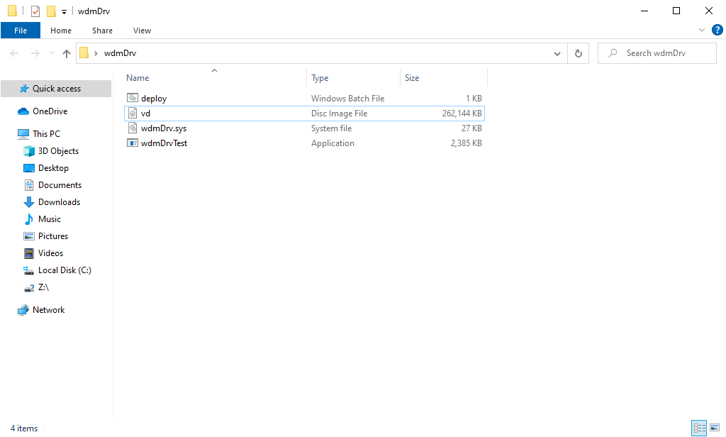
Now we can open the disk, which will cause the formatting window to appear. It allows us to format the disk with the required file system. Then we can create several files on the disk and go back to the wdmDrvTest.exe application and press any button to unmount the disk. To mount the disk from the file once more, we need to remove the –create parameter from the command above. After running the changed command as an administrator, the disk will appear in File Explorer again, but now with all the files created earlier.
To check if the data on the disk is encrypted, we can try opening the vd.img file with FTK Imager:
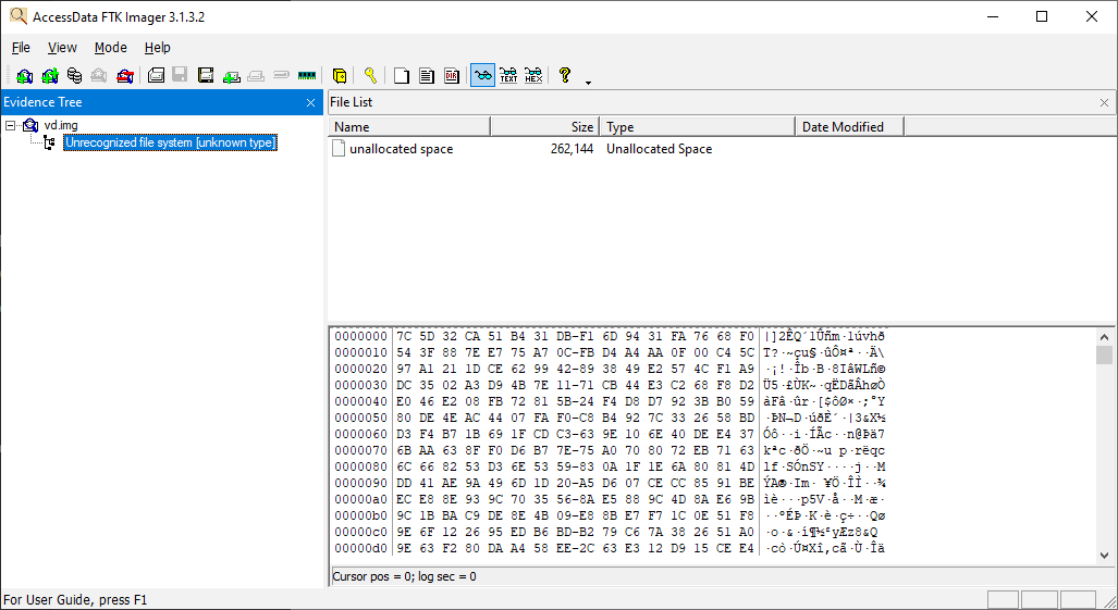
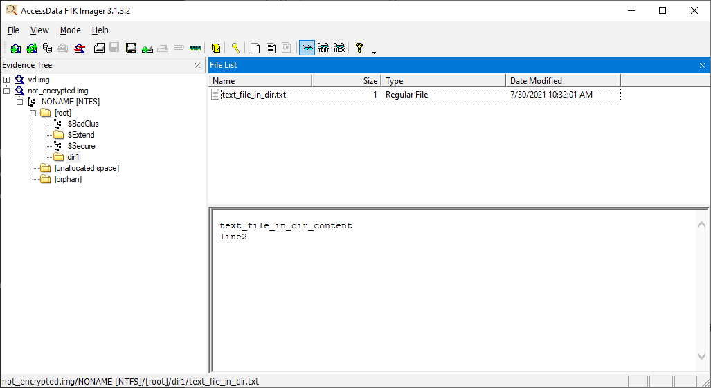
If we turn off encryption, we’ll be able to see all of the contents of our virtual disk:
Finalizing the implementation of WDM requirements
Currently, we have a legacy driver. To turn it into a Windows Driver Model driver, we need to introduce the following changes:
- Create the inf file
- Create the AddDevice routine
- Create callbacks for additional IRPs
To make these changes. Let’s use the toastMon sample from WDK 7600.16385.1. Note that the toaster’s version on GitHub already uses the Kernel-Mode Driver Framework (KMDF).
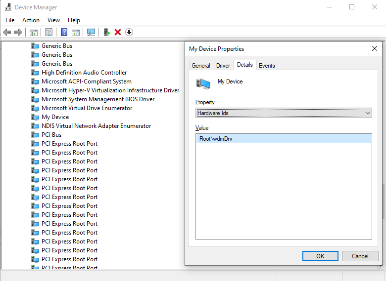
First, we update the inf file created by default in the beginning. This file contains HardwareID 一 Root\wdmDrv, which the system uses to find a driver which will serve this device:
[Manufacturer]
%ManufacturerName%=Standard,NT$ARCH$

[Standard.NT$ARCH$]
%DeviceDesc%=wdmDrv_Device, Root\wdmDrv

[Strings]
ManufacturerName="VvCorp"
DeviceDesc= "My Device"Now, if we try to install inf without changes in the driver, we’ll see the Unable to find any matching devices error in C:\Windows\INF\setupapi.dev.log.
Next, let’s add the AddDevice callback and specify its address in DriverEntry:
DriverObject->DriverExtension->AddDevice = AddDevice;Here’s how the system calls the DriverEntry function:
00 wdmDrv!DriverEntry
01 wdmDrv!GsDriverEntry
02 nt!PnpCallDriverEntry
03 nt!IopLoadDriver
04 nt!PipCallDriverAddDeviceQueryRoutine
05 nt!PnpCallDriverQueryServiceHelper
06 nt!PipCallDriverAddDevice
07 nt!PipProcessDevNodeTree
08 nt!PiRestartDevice
09 nt!PnpDeviceActionWorker
0a nt!ExpWorkerThread
0b nt!PspSystemThreadStartup
0c nt!KiStartSystemThreadAfter that, the system calls the AddDevice function for the device which is defined in the inf file:
00 wdmDrv!AddDevice
01 nt!PpvUtilCallAddDevice
02 nt!PnpCallAddDevice
03 nt!PipCallDriverAddDevice
04 nt!PipProcessDevNodeTree
05 nt!PiRestartDevice
06 nt!PnpDeviceActionWorker
07 nt!ExpWorkerThread
08 nt!PspSystemThreadStartup
09 nt!KiStartSystemThreadNow, we have to create our control device in the AddDevice routine instead of DriverEntry. After this, we’ll attach our created control device to the device stack using the following call:
deviceExtension->TopOfStack = IoAttachDeviceToDeviceStack(
        gDeviceObject,
PhysicalDeviceObject);Let’s take a closer look at the elements from the example above:
- PhysicalDeviceObject (PDO) is the device for \Driver\PnpManager, which we received from the system in AddDevice arguments
- gDeviceObject is the control device we created
Here’s how the device stack in WinDbg looks like once the device is successfully attached to the stack:
The call mentioned above also sets the StackSize field for our control device, making it 2: PDO->StackSize+1. And deviceExtension->TopOfStack will hold PhysicalDeviceObject. We’ll use it to pass IRPs down to the stack.
Next, we specify callbacks for PnP, Power Management, and Windows Management Instrumentation (WMI):
DriverObject->MajorFunction[IRP_MJ_PNP]=DispatchPnp;
DriverObject->MajorFunction[IRP_MJ_POWER]=DispatchPower;
DriverObject->MajorFunction[IRP_MJ_SYSTEM_CONTROL]=DispatchSystemControl;For Power Management and WMI, we only forward the IRP to the next device in the stack.
As for PnP, after AddDevice the system will call the DispatchPnp routine. Here, we are only interested in IRP_MN_START_DEVICE and IRP_MN_REMOVE_DEVICE IRPs (see below). We need to wait for IRP completion by PDO. For that, let’s set our CompletionRoutine and pass IRP down to PDO. When PDO completes IRP, all devices in the stack will be started. So our upper device can finish its start activity:
00 wdmDrv!CompletionRoutine
01 nt!IopfCompleteRequest
02 nt!IofCompleteRequest
03 nt!IopPnPCompleteRequest
04 nt!IopPnPDispatch
05 nt!IofCallDriver
06 wdmDrv!DispatchPnp
07 nt!IofCallDriver
08 nt!PnpAsynchronousCall
09 nt!PnpSendIrp
0a nt!PnpStartDevice
0b nt!PnpStartDeviceNode
0c nt!PipProcessStartPhase1
0d nt!PipProcessDevNodeTree
…Now, we can install our driver using the inf file and the Device Console (DevCon) tool from WDK:
> devcon.exe install wdmDrv.inf Root\wdmDrvAfter that, our driver will be displayed in Device Manager:
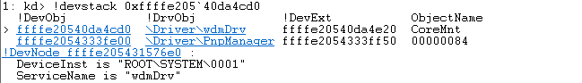
We can also see our device in the PnP tree in WinDbg by using “!devnode 0 1” command:
DevNode 0xffffd988b0e0fcc0 for PDO 0xffffd988b23022e0
    InstancePath is "ROOT\SYSTEM\0001"
    ServiceName is "wdmDrv"
    State = DeviceNodeStarted (0x308)
Previous State = DeviceNodeEnumerateCompletion (0x30d)To uninstall device, execute:
> devcon remove Root\wdmDrvOur driver will receive IRP_MN_REMOVE_DEVICE IRP and the stack will look like this:
00 wdmDrv!DispatchPnp
01 nt!IofCallDriver
02 nt!IopSynchronousCall
03 nt!IopRemoveDevice
04 nt!PnpRemoveLockedDeviceNode
05 nt!PnpDeleteLockedDeviceNode
06 nt!PnpDeleteLockedDeviceNodes
07 nt!PnpProcessQueryRemoveAndEject
08 nt!PnpProcessTargetDeviceEvent
…Now, let’s delete our control device here instead of DriverUnload. And after this IRP, our driver will be unloaded from memory.
As you can see, WDM requires handling of additional IRPs for PnP, Power Management, and WMI. If you use KMDF, all of these will be under the hood. So, instead of writing boilerplate code which can potentially have bugs, it would be better to use KMDF. But first, you’ll need to determine which type of driver you need. In our case, a legacy driver was enough. Note: if you need to monitor filesystem activity, for example, you also don’t need KMDF. Consider going with a minifilter driver in such a case.
Now, we can move to the final stage of the driver development process and debug our driver.
Debugging the disk
First, we need to install the WinDbg tool. It comes as part of Windows SDK and WDK, although you can also install it separately by checking only the Debugging tools for Windows option during setup.
Microsoft recommends using the Hyper-V hypervisor for driver debugging. They also provide a detailed guide on a simplified debugging process for Windows, which has Hyper-V built in. Recommendations on how to enable Hyper-V and configure a virtual machine with it are also provided on the Microsoft website. Alternatively, you can debug a driver using VirtualKD.
Since we created our virtual machine using VMWare, we use a slightly different approach:
1. Choose Add -> Serial Port in the settings of the virtual machine and check the boxes as shown in the following screenshot:
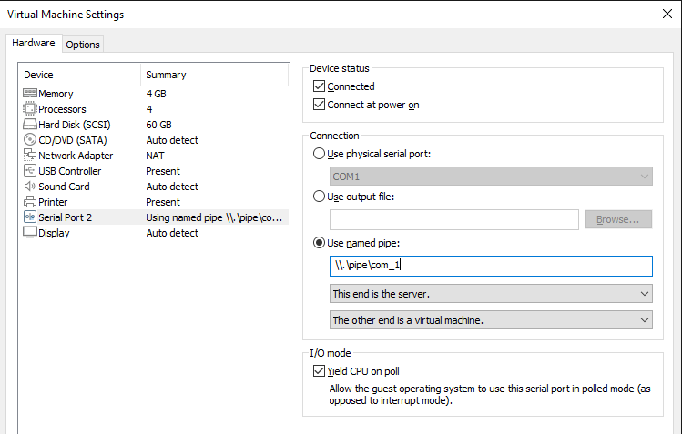
The name com_1 will be used in the WinDbg connection settings, so you can change it to a different one.
2. Start the virtual machine and run the following commands as an administrator:
> bcdedit /debug on
> bcdedit /dbgsettings serial debugport:2 baudrate:1152003. On the machine with WinDbg installed, run the following command as an administrator:
> setx _NT_SYMBOL_PATH srv*c:\symbols*http://msdl.microsoft.com/download/symbolsThis command adds the environment variable indicating where to look for the symbols (.pdb).
4. Create a WinDbg shortcut and add Target parameters at the end to launch kernel debugging:
-k com:pipe,port=\\.\pipe\com_1,resets=0,reconnectMake sure to change the pipe name when you repeat these actions on your virtual disk.
5. Double-click on the WinDbg shortcut and restart the virtual machine.
Once the system restarts, we can:
- Open WinDbg and press Ctrl+Break
- Specify the path to the pdb driver using the .sympath+ command
- Run the commands listed in this article once again to better memorize the described approach
And that’s it. We’ve successfully created a Windows WDM driver.
To learn details about drivers, check out our articles about Windows driver testing and USB WiFi driver development.
How Apriorit helps you build custom drivers
Developing Windows drivers is one of our core areas of expertise. With over 20 years of experience in this field, we can help you build a custom Windows driver or make an existing driver bug-free and compatible with Windows 11. We’ll pay special attention to matching your security, performance, and integration requirements.
Here’s why our clients choose Apriorit for custom driver development:
- Experience in C/C++ and Rust driver development. Traditionally, driver development was based on C/C++. In recent years, we’ve seen a trend for writing drivers in Rust, especially in IoT, robotics, and automotive projects. Apriorit can provide you with a team that has real driver development experience in any of these languages. Our skills cover developing drivers from scratch, maintaining and improving existing drivers, and migrating to a new tech stack.
- Access to rare expertise. Apriorit will provide you with experts in kernel driver development, reverse engineering, cybersecurity, and other niche development areas. Hiring such talents is usually a long and challenging process. Working with us, you can skip employee search and onboarding and get your project off the ground quickly.
- Mature development and delivery processes. With over 20 years of experience delivering solutions for clients in highly regulated industries and markets, we’ve perfected our internal processes to consistently provide you with the best results.
- HLK testing and driver preparation for WHQL certification. Getting WHQL certification is crucial for any Windows driver. Our team will help you prepare your driver for testing, guide you through this process, and ensure certification.
- Cybersecurity-driven mindset. As a cybersecurity-first company, protecting your sensitive data and IP is our top priority. We enforce a secure SDLC workflow in all of our projects and comply with requirements of ISO 27001, the GDPR, and other common regulations and standards.
- Flexible cooperation models. Driver development projects usually require a dedicated team. However, depending on your project’s goals and timeline, we can also offer fixed price or time and materials cooperation models.
Real-life examples always speak louder than promises, so let us share some of our driver development projects.
Case #1. Improving a Windows audio driver to pass WHQL testing
A British audio technology company asked us to optimize their existing driver, improve its performance, and fix security-related issues. With our help, they wanted to improve the audio experience for their end users, pass WHQL testing, and release their application for Windows.
Apriorit helped them by:
- Testing the driver according to WHQL requirements
- Reworking the driver to fix all discovered bugs and vulnerabilities, including issues with security, performance, and third-party compatibility
- Stabilizing and optimizing the client’s app that works with the driver
- Helping the client pass tests and acquire a WHQL release signature
Case #2. Building drivers for low-latency VR headsets
A manufacturer of virtual reality (VR) equipment for professional training on aircraft navigation and medical assistance required hardware that worked seamlessly and in real time.
At their request, we developed a custom data transmission protocol and a Windows device driver that:
- Complied with the client’s tight deadlines for device release
- Allowed the device to operate with 3–10 ms of latency and ~11 Gbps data transmission speed
- Passed WHQL certification and was fully compatible with Windows 10
- Received positive feedback from customers
Case #3. Developing a driver solution for blocking USB devices
A leading US-based provider of enterprise-grade encryption solutions asked us to help them secure USB connections with their products. They were looking for a team that could build a custom driver for Windows and macOS that would be compatible with other clients’ solutions and block a wide range of USB devices based on sets of rules.
Here’s how we helped them:
- Ported the existing USB blocking SDK to Windows and built a macOS solution to save time
- Made UI improvements and added features including read-only access, tray notifications, and default allowlists
- Improved user data security by adding support for UASP storage devices and VDI environments
- Tested and ensured the driver’s compatibility with the client’s system
Conclusion
Software drivers play an essential role in building Windows applications and expanding their capabilities. This process requires Windows driver developers to have a deep understanding of driver development specifics, keen knowledge of Windows internals, and expertise in C/C++.
Apriorit driver development professionals have successfully helped many businesses tackle their driver development challenges and deliver well-performing, secure, and competitive products.
Looking for quick access to rare driver development talents?
Benefit from our extensive 20-year track record in specialized driver development to reinforce your product and broaden its features!
FAQ
What is the Windows Driver Model (WDM)?
The Windows Driver Model (WDM) is a framework for device drivers that was introduced to provide a common architecture for Windows 98 and later versions. It enables developers to build drivers that are compatible with multiple versions of Windows, ensuring hardware compatibility and stability.
What are the key components of a WDM driver?
<p>A WDM driver typically consists of:</p>
<ul class=apriorit-list-markers-green>
<li>DriverEntry routine that initializes the driver</li>
<li>Dispatch routines that handle various I/O requests</li>
<li>I/O request packets that communicate between the driver and the OS</li>
</ul>
What are common challenges in developing WDM drivers?
<p>WDM driver development requires expertise, precision, and practice from developers. Common challenges include:</p>
<ul class=apriorit-list-markers-green>
<li>Handling synchronization and concurrency</li>
<li>Managing memory efficiently</li>
<li>Ensuring compatibility with different versions of Windows</li>
</ul>
<p>Additionally, debugging and testing drivers can be complex and time-consuming.</p>
How can you ensure the security and stability of my WDM driver?
<p>At Apriorit, we leverage our 20+ years of experience to assess and mitigate the risks associated with any driver development project.</p>
<p>Using tools like Driver Verifier helps us identify potential issues with driver security and stability. To prevent or fix them, we follow Microsoft’s driver development guidelines and internal best practices such as validating all inputs, handling errors gracefully, and performing thorough testing.</p>
What resources do you use for WDM driver development?
We start with official resources like Microsoft documentation. And as the Apriorit team is part of the larger driver development community, we often rely on community guidance for challenging or rare tasks. Finally, we have an internal knowledge base and NDA-compliant practices for sharing knowledge among our teams.
Have a question?
Ask our expert!
Program Manager