Skip to main content
A bootloader is a small but extremely important piece of software that helps a computer boot an operating system (OS). Creating one is a challenging task even for a skilled low-level developer. That’s why Apriorit driver development experts decided to share their experience on the subject.
In this article, we overview the theory of system loading and show you how to write a bootloader. You can check out the solution we describe in this tutorial in our GitHub repository.
This article will be useful for developers working with high-level languages like C and C++ who need to learn how to develop a bootloader.
Contents:
Stage 1: Preparing for bootloader development
Let’s start with a quick overview of bootloader development basics.
A bootloader is a piece of software located in the first sector of a hard drive where system booting starts. This sector is also known as the master boot record (MBR). Computer firmware reads the data contained in this first sector and processes it to the system memory when the machine is powered up. When the firmware finds the bootloader, it loads it and the bootloader initiates the launch of the OS.
The boot sector is usually the first sector of the disk. This isn’t obligatory for a modern boot system, but most developers place the bootloader in the first sector. So for now, we’ll stick to the first sector as well. But keep in mind, that a boot sector is required only for BIOS-based systems.
Choosing a firmware interface: UEFI vs BIOS
You can develop a bootloader for a Basic Input/Output System (BIOS) or Unified Extensible Firmware Interface (UEFI). A BIOS is well-known computer hardware supported by all devices. UEFI is a modern BIOS replacement provided on modern hardware that gives developers many more options for low-level development.
Key advantages of working with UEFI instead of BIOS:
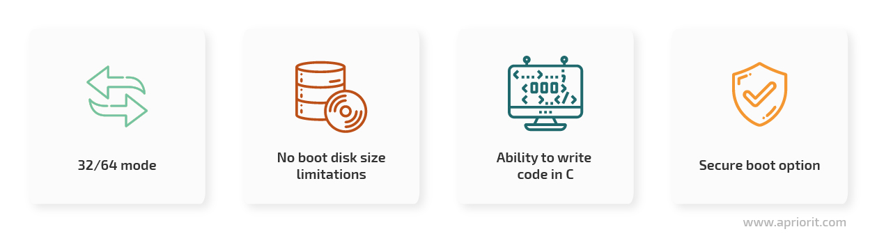
- The ability to work in 32/64 mode allows you to access more processor functionalities, while BIOS works in 16-bit mode only.
- No boot disk size limitations allow you to use any disk to boot the system.
- Writing code directly in C using complete development environments such as EDK2 eliminates the need to study assembler or mix high-level and low-level code.
- Secure boot verifies that a device boots using only trusted software that has electronic signatures.
But despite all these advantages, in this tutorial, we’ll be developing a BIOS bootloader from scratch. The first reason for this is because BIOS is supported by a wider range of hardware. Furthermore, almost all old devices support BIOS only. Secondly, all UEFI-compatible systems can behave like BIOS systems in legacy mode, so you’ll be able to run our bootloader on UEFI systems as well.
Does your project require low-level development?
Entrust your project to Apriorit’s skilled team. We will help you develop and test low-level projects of any complexity, meeting all of your requirements.
Understanding the system booting process
Next, we need to gain a general understanding of the system booting process. This is how components interact with each other when you boot the system:
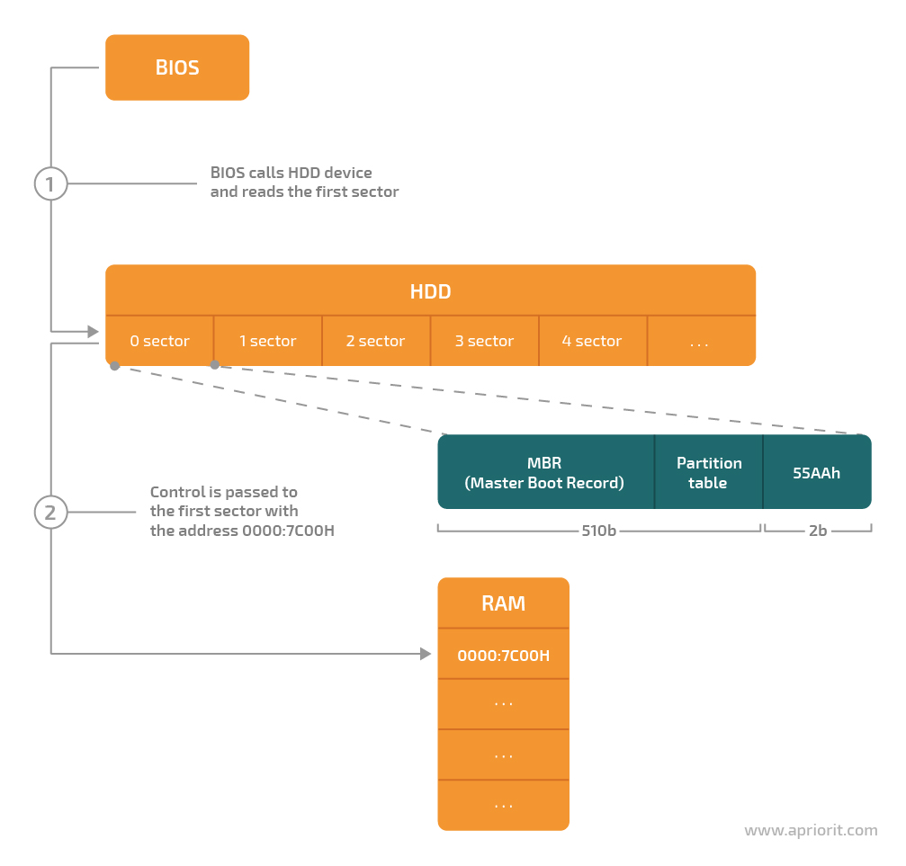
Figure 1. The system booting process
- The BIOS reads the first sector of the hard disk drive (HDD).
- The BIOS passes control to the MBR located at the address 0000:7c00, which triggers the OS booting process.
After that, the booting process is over and the OS starts.
Choosing a language in which to develop the bootloader
Most commonly used languages use a virtual machine to convert intermediate code into language understood by the processor. You can execute that intermediate code only after it’s converted. The only exceptions are hypothetical cases when you implement all required runtime code by yourself using some set of native languages.
When developing a bootloader, you need a language that doesn’t depend on the runtime. You can’t use runtime-dependent languages like Java and C# because they produce intermediate code after compilation.
To avoid this challenge, we’ll use C++ as the main language for low-level programming in this bootloader development tutorial.
Also, knowing the basics of how to work with an assembler is a great advantage when writing a bootloader. During the initial stages of computer operation, the BIOS takes control of the machine hardware via functions called interrupt calls, which are written in an assembler language. It’s not obligatory to know the assembler language when building a bootloader, since we can mix low-level language commands and high-level constructions. But knowing it is essential for debugging the written bootloader.
Selecting the tools
To be able to mix high-level and low-level code and write your own bootloader, you’ll need at least three tools:
- Compiler for the assembler
- C++ compiler
- A linker
A processor functions in 16-bit real mode with certain limitations and in 32-bit safe mode with full functionality. When you turn on a computer, its processor operates in real mode. That’s why building a program and creating an executable file requires an assembler compiler and linker that can work in 16-bit mode.
A C++ compiler is required only to create *.obj files in the 16-bit real mode.
Note: The latest compilers are not suitable for our task, as they’re designed to run in 32-bit safe mode only.
After testing several 16-bit compilers, we chose Microsoft compilers and linkers for this tutorial. We used them to build all low-level language code examples and other cited code. The Microsoft Visual Studio 1.52 package already contains what we need: a compiler and a linker for assembler and C++.
Here are the linkers and compilers you can use to develop a custom bootloader instead of the tools we use in the tutorial:
| Assembler compilers | C/C++ compilers | Linkers |
| ML 6.15
16-bit compiler by Microsoft | CL
16-bit compiler | LINK 5.16
16-bit linker for creation of *.com files |
| DMC
free compiler by Digital Mars | DMC
free compiler by Digital Mars | LINK
free linker designed to work with the DMC compiler |
| TASM
16-bit compiler by Borland | BCC 3.5
16-bit compiler by Borland | TASM
16-bit linker for creation of *.com files by Borland |
Note: If you have any problems using the cl.exe file provided in our GitHub repository, you may try using the DMC compiler instead.
Read also
How to Develop a Windows Minifilter Driver to Back Up Data
Examine a step-by-step minifilter driver development tutorial with our expert advice to get ready for your next low-lever project.

Stage 2: Developing the bootloader
We’re going to build a basic bootloader that performs three simple tasks:
- Loads bootloader instructions from the 0000:7c00 address to the system memory.
- Calls the BootMain function written in a high-level language.
- Displays a “Hello world” message on the screen.
The architecture of our bootloader looks like this:
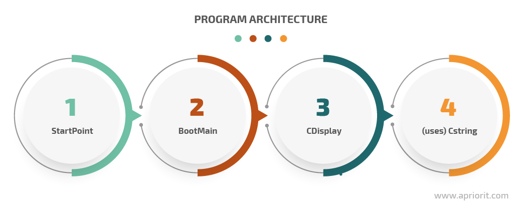
Figure 2. Bootloader architecture
The first element is StartPoint. This entity is written in an assembler language because high-level languages lack the required instructions. StartPoint instructs the compiler to use a specific memory model and lists the addresses for loading to RAM after data from the disk is read.
BootMain is an entity similar to the main element written in a high-level language that takes control right after StartPoint.
Finally, CDisplay and CString come in. Their role is to display the message. As you can see from Figure 2, they aren’t equal, as CDisplay uses CString.
Setting up the environment
To develop our bootloader, we need compilers, linkers, and their dependencies. We’ll also use Microsoft Visual Studio 2019 to make the process more convenient.
To start configuring the environment, we need to create a project using the Makefile Project template. In Microsoft Visual Studio, choose File > New > Project > General and select Makefile Project. Then click Next.
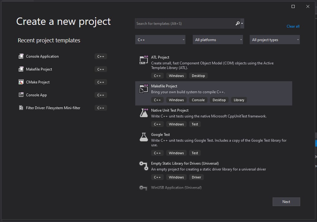
Figure 3. Creating a new project in Microsoft Visual Studio 2019
BIOS interrupts and screen cleaners
Before our bootloader can display the message, the screen must be cleared. Let’s use a BIOS interrupt for this task.
The BIOS provides various interrupts that allow for interacting with computer hardware: input devices, disk storage, audio adapters, and so on. An interrupt looks like this:
int [number_of_interrupt];Here, the number_of_interrupts is the interrupt number. In this tutorial, you’ll need the following interrupts:
int 10h, function 00h– This function changes the video mode and thus clears the screenint 10h, function 01h– This function sets the type of the cursorint 10h, function 13h– This function concludes the whole routine by displaying a string of text on the screen
Before you call an interrupt, you must first define its parameters. The ah processor register contains the function number for an interrupt, while the rest of the registers store other parameters of the current operation. For example, let’s see how the int 10h interrupt works in an assembler. You need the 00h function to change the video mode, which will result in a clear screen:
mov al, 02h ; here we set the 80x25 graphical mode (text)
mov ah, 00h ; this is the code of the function that allows us to change the video mode
int 10h ; here we call the interruptMixing high-level and low-level code
One of the advantages of the C++ compiler is that it has an inbuilt assembler translator, which allows you to write low-level code in a high-level language. Assembler instructions written in high-level code are called asm insertions. They’re marked with the introductory string _asm followed by a block of assembler instructions enclosed in braces. Here’s an example of a low-level language code insertion:
__asm ;  this is a keyword that introduces an asm insertion
  { ;  the beginning of a block of code
  … ; some asm code
} ; the end of the block of codeNow we combine the C++ code with the assembler code that clears the screen to illustrate the mixed code technique:
void ClearScreen()
{
 __asm
{
 mov al, 02h ; here you set the 80x25 graphical mode (text)
mov ah, 00h ; this is the code of the function that allows us to change the video mode
int 10h   ; here you call the interrupt
}
}With this knowledge of the OS booting process, we can move on to developing the elements of our bootloader.
Read also
How to Develop a Minimal OS for Raspberry Pi 3 in Rust
Embedded systems have limited computing resources, so software for them needs to be extremely efficient. Discover how to develop such software, which tools to choose, and what to prioritize in its design.
Implementing bootloader structure elements
After you learn more about BIOS interrupts and mixed code, you can start implementing bootloader components. Let’s start with StartPoint.asm:
;------------------------------------------------------------
.286                 ; CPU type
;------------------------------------------------------------
.model TINY               ; memory of model
;---------------------- EXTERNS -----------------------------
extrn        _BootMain:near     ; prototype of C func
;------------------------------------------------------------
;------------------------------------------------------------
.code
org        07c00h       ; for BootSector
main:
        jmp short start     ; go to main
        nop

;----------------------- CODE SEGMENT -----------------------
start:
        cli
        mov ax,cs               ; Setup segment registers
        mov ds,ax               ; Make DS correct
        mov es,ax               ; Make ES correct
        mov ss,ax               ; Make SS correct
        mov bp,7c00h
        mov sp,7c00h            ; Setup a stack
        sti
                                ; start the program
        call           _BootMain
        ret

END main ; End of programBootMain is the main function that serves as the starting point of the program. This is where the main operations take place. For our bootloader, this function looks like this:
// BootMain.cpp
#include "CDisplay.h"
#define HELLO_STR               "\"Hello, world…\", from low-level..."
extern "C" void BootMain()
{
    CDisplay::ClearScreen();
    CDisplay::ShowCursor(false);
    CDisplay::TextOut(
        HELLO_STR,
        0,
        0,
        BLACK,
        WHITE,
        false
        );
    return;
}The CDisplay class handles interactions with the screen. It consists of the following methods:
- ShowCursor controls the cursor manifestation on the display. It has two values: show and hide, which enable and disable the cursor manifestation respectively.
- TextOut produces the text output, i.e. displays a string on the screen.
- ClearScreen clears the screen by changing the video mode.
Here’s the implementation of the CDisplay class:
// CDisplay.h
#ifndef __CDISPLAY__
#define __CDISPLAY__
//
// colors for TextOut func
//
#define BLACK      0x0
#define BLUE      0x1
#define GREEN      0x2
#define CYAN      0x3
#define RED        0x4
#define MAGENTA      0x5
#define BROWN      0x6
#define GREY      0x7
#define DARK_GREY      0x8
#define LIGHT_BLUE    0x9
#define LIGHT_GREEN    0xA
#define LIGHT_CYAN    0xB
#define LIGHT_RED          0xC
#define LIGHT_MAGENTA     0xD
#define LIGHT_BROWN    0xE
#define WHITE      0xF
#include "Types.h"
#include "CString.h"
class CDisplay
{
public:
    static void ClearScreen();
    static void TextOut(
        const char far* inStrSource,
        byte            inX = 0,
        byte            inY = 0,
        byte            inBackgroundColor   = BLACK,
        byte            inTextColor         = WHITE,
        bool            inUpdateCursor      = false
        );
    static void ShowCursor(
        bool inMode
        );
};
#endif // __CDISPLAY__
// CDisplay.cpp
#include "CDisplay.h"
void CDisplay::TextOut(
        const char far* inStrSource,
        byte            inX,
        byte            inY,
        byte            inBackgroundColor,
        byte            inTextColor,
        bool            inUpdateCursor
        )
{
    byte textAttribute = ((inTextColor) | (inBackgroundColor << 4));
    byte lengthOfString = CString::Strlen(inStrSource);
    __asm
    {
        push  bp
        mov    al, inUpdateCursor
        xor    bh, bh
        mov    bl, textAttribute
        xor    cx, cx
        mov    cl, lengthOfString
        mov    dh, inY
        mov    dl, inX
        mov     es, word ptr[inStrSource + 2]
        mov     bp, word ptr[inStrSource]
        mov    ah,  13h
        int    10h
        pop    bp
    }
}
void CDisplay::ClearScreen()
{
    __asm
    {
        mov     al, 02h
        mov     ah, 00h
        int     10h
    }
}
void CDisplay::ShowCursor(
        bool inMode
        )

{
    byte flag = inMode ? 0 : 0x32;
    __asm
    {
        mov     ch, flag
        mov     cl, 0Ah
        mov     ah, 01h
        int     10h
    }
}The CString class works with strings. The value of the string it contains will be used by the CDisplay class. Let’s implement the Strlen method of this class. This method passes a pointer to a string as its parameter, counts the number of characters in the obtained string, and returns the resulting number. The implementation looks like this:
// CString.h
#ifndef __CSTRING__
#define __CSTRING__
#include "Types.h"
class CString
{
public:
    static byte Strlen(
        const char far* inStrSource
        );
};
#endif // __CSTRING__
// CString.cpp
#include "CString.h"
byte CString::Strlen(
        const char far* inStrSource
        )
{
        byte lenghtOfString = 0;

        while(*inStrSource++ != '\0')
        {
            ++lenghtOfString;
        }
        return lenghtOfString;
}Now, you can move on to assembling the program.
Stage 3: Assembling the bootloader
Once you’ve finished writing the bootloader code, it’s time to convert it to a .com file that can work on a 16-bit OS. First, you need to start the assembler and C++ compilers using the command line. After that, you need to pass the required parameters to the compiler. As a result, you’ll receive object files.
Next, a linker comes in. You need it to merge the object files into a single .com executable file.
Now, let’s automate the assembly process. To do that, you simply need to create a .bat file with all necessary commands and parameters. The whole process of assembling an application looks like this:
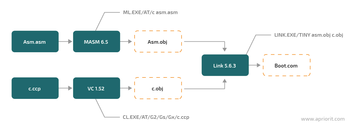
Figure 4. Assembling the bootloader
The compilers and the linker must be placed in the project folder. In this folder, you also need to place a .bat file with the following content:
.\VC152\CL.EXE /AT /G2 /Gs /Gx /c /Zl *.cpp .\VC152\ML.EXE /AT /c *.asm .\VC152\LINK.EXE /T /NOD StartPoint.obj bootmain.obj cdisplay.obj cstring.obj del *.objV152 is the name of the folder with the compilers and the linker. You can rename it, but the rest of the content must remain unchanged.
We can also use Microsoft Visual Studio as the development environment for this example. A great advantage of Visual Studio is that it supports any compiler. To start the compilation process, open Project > Properties > Configuration PropertiesGeneral > Configuration Type.
In the Configuration Properties section, click the NMake page. Then, enter the path to the build.bat file in the Build command line and Rebuild command line boxes as shown in the screenshot below:
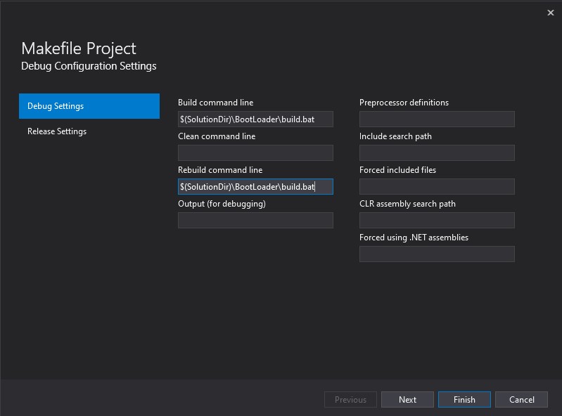
Figure 5. Configuring the Makefile project
Once you’ve done this, you can start the compilation as usual by pressing F7 or the Ctrl+F7 hotkey. During the process, all accompanying information is displayed in the Output window.
Read also
How to Develop a Windows Driver Using a QEMU Virtual Device
Leverage virtualization techniques to develop and test low level software for devices that you don’t physically have.
Stage 4: Testing the bootloader on a VM and real hardware
You can test a bootloader on a physical machine or a virtual machine (VM) configured for this task. By testing on a physical machine, you can verify that the bootloader works and assess its performance.
The key advantage of testing the software on a virtual machine is that it’s safer, as you can fix any issues on the VM quickly or create a new VM. However, this type of testing doesn’t allow you to check the performance of the bootloader.
In this tutorial, we’ll overview both methods.
First, you need a tool for writing a bootloader to a virtual or physical drive. Depending on your needs and resources, you can pick up either a console- or interface-based tool. Our choice is Disk Explorer for NTFS 3.66 (you can also find a version for the FAT file system) and Norton Disk Editor 2002 for MS-DOS.
Testing on a virtual machine
1. Before testing, you need to create a virtual machine. You can do it using VMware 5.0 or higher. The minimum disk space of a VM for bootloader testing is 1GB. Since we’re using a tool for the NTFS file system, we need to format the allocated space to NTFS.
2. Map the drive to VMware to make it a virtual drive. Go to File > Map or Disconnect Virtual Drives and click the Map In the Map Virtual Disk window, specify the path to the disk in the File name box and select the drive partition label in the Drive box.
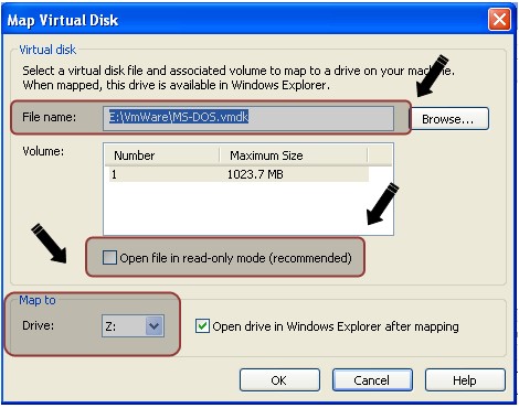
Figure 6. Mapping a virtual drive
Make sure to clear the Open file in read-only mode checkbox. This option prevents data corruption by prohibiting writing data to the disk. You can leave the rest of the options unchanged.
This quick setup allows us to work with a virtual disk as we would with a regular Windows logical disk.
3. You can record your bootloader at the 0 physical offset using Disk Explorer for NTFS 3.66. To do that, go to File > Drive and select the virtual drive. In the Select drive window, open the Logical drives group and select the drive with the label you previously defined.
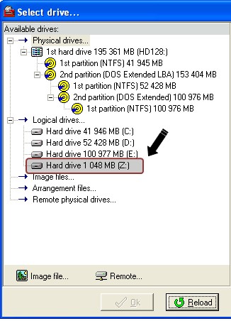
Figure 7. Selecting the mapped drive
Then, select View > As Hex. In the Hex View window, the 16-bit representation of the disk is displayed. The content is divided by offsets and sectors. As the disk is empty at the moment, there are only 0s.
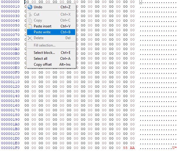
Figure 8. An empty disk in the Hex View panel
4. Let’s write the bootloader to the first sector of the drive. Move the marker to the 00 position as illustrated in the screenshot above. Select Edit > Paste from file, specify the path to the file whose contents must be written to the selected position, and click Open. This will paste the bootloader. The contents of the first sector will change accordingly (see the screenshot below; unless you’ve made some modifications to the code, the contents will be the same).
Now you need to instruct the BIOS to identify the first sector as the boot sector and load it to memory. For this purpose, you need to add the 55AAh signature at the 1FE offset that marks the beginning of. To do this, press the F2 hotkey to enter the editing mode and write the required characters of the signature at the defined offset. After you’re finished editing, press Esc.
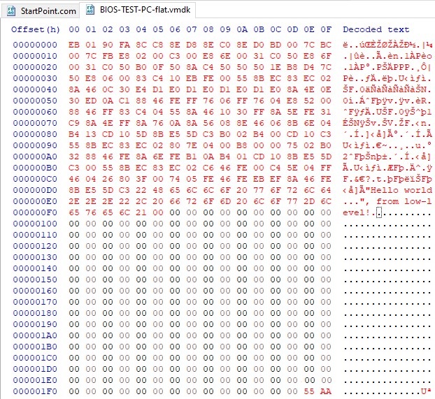
Figure 9. Hex View panel of a disk containing the bootloader
To confirm the data writing, select Tools > Options. In the Options window, select the Virtual write mode and click Write. This mode allows for making modifications that will be stored only in memory.
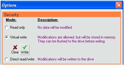
Figure 10. Confirming data writing
Then disconnect the virtual disk in VMware by going to File > Map or Disconnect Virtual Disks and clicking Disconnect.
Now, let’s run the virtual machine and behold this moment of triumph when our efforts at writing low-level code result in “Hello world…”, from low-level! on the screen.
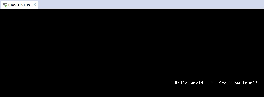
Figure 11. The bootloader is working!
Finally, let’s see if we can achieve the same success when testing our bootloader on a physical machine.
Read also
How to Develop a Windows File System Minifilter Driver: Complete Tutorial
Explore all nuances of minifilter drivers that will show open files in the debug output, as well as reasons to use minifilters in low-level Windows development.
Testing on a physical machine
The process of testing a bootloader on a physical machine is almost identical to testing it on a virtual machine. To write a bootloader to a flash drive using Disk Explorer for NTFS, you need to perform all the steps described above and only change step three a bit. In particular, you need to select a whole physical drive instead of a logical partition so that writing is performed at the correct offset.
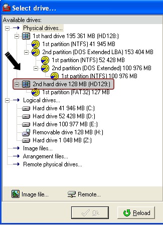
Figure 12. Selecting a physical drive for testing
You can also use a flash drive instead of a hard drive to avoid data corruption. But before you do that, restart your computer, boot into the BIOS, and make sure that your BIOS supports flash drives. If it doesn’t, the only safe solution for you is to perform testing on a virtual machine.
Tools for bootloader debugging
Make sure to have the proper debugging tools for your bootloader. Also, keep in mind that debugging can take the same amount of time as development. You’ll also need to dive deep into the assembler machine code. Good knowledge of the assembler language is obligatory at this point.
The following debugging tools will come in handy:
- Turbo Debugger by Borland is a great debugging solution for 16-bit mode
- CoveView is a 16-bit debugger embedded in Microsoft Visual Studio
- D86 is a good 16-bit debugger by Eric Isaacson, a programmer experienced in assembler development for Intel
- Bochs is a virtual machine program emulator with a built-in debugger for machine commands.
Conclusion
In this tutorial, we’ve shown you how to create a simple but operational bootloader and test it in a virtual machine and on physical devices. Using our guide, you can gain a deeper understanding of system booting processes and improve your low-level development skills. Feel free to use the source code of our bootloader from this GitHub repository.
Plan a challenging system development project?
Reach out to Apriorit’s development team to leverage our skills in designing, developing, testing, and maintaining low-level systems.
Have a question?
Ask our expert!
Program Manager