Skip to main content
Quality images are crucial for various solutions including security and vehicle camera systems, as well as for developing and training machine learning algorithms for image processing tasks.
However, physical camera sensors often create distortions in photos. These distortions can significantly decrease image quality and even make images impossible for your solution to process.
In this article, we explore what image distortions are and why it’s important to remove them. We also show how to fix image distortions using OpenCV. This text will be helpful for businesses and development teams working on IT solutions with image processing functionalities who want to learn more about fixing image distortions.
Contents:
What are image distortions and how can they affect your solution’s performance?
Image distortion is usually a non-proportional, inadequate deviation of a graphical image from its real-life prototype. For instance, lines that are straight or parallel in real life may appear deformed or unnaturally curved. Another example is lighting-related distortions, such as when colors get darker towards the borders of an image, similar to vignetting.
Not all distortions are unfavorable. For example, you might want to keep a specific distortion in an image taken with a wide-angle lens to highlight the distance between the foreground and background.
However, more often than not, you need your camera to take precise images. For some technologies, it’s crucial to have images with zero distortions.
Ensuring distortion-free images is extremely important for developing machine learning (ML) solutions and training artificial intelligence (AI) networks for image processing tasks.
The training dataset must be consistent (similar examples must have similar markers) and uniform (values of all attributes must be comparable across all data). Datasets of poor quality will reduce the efficiency of an AI algorithm’s training process.
There are scenarios in which distorted images can be placed in a dataset on purpose. For example, you might want to train algorithms to process images taken by different cameras with different distortions. However, if images from different cameras have significant differences in the form and degree of distortions, then including such images in one dataset will break the consistency and uniformity requirement. Thus, it will be impossible to efficiently train an AI algorithm to provide the desired results.
Image quality is also essential for software that uses computer vision and augmented reality (AR) technologies.
Say you’re working with a complex solution that uses two or more cameras to take photos from different angles. You might need to combine several images to receive a three-dimensional image like those used in 360-degree camera systems in vehicles. Or you may want to expand the view by stitching several photos to produce a high-resolution panoramic image of an entire scene. Without calibrating (resectioning) camera sensors, the stitch between connected images will be visible.
To resolve those issues, you need to fix image distortions. Before we discuss how to do it, let’s briefly explore the common types of such distortions.
Drive innovation with AI development while prioritizing cybersecurity!
Partner with us to integrate advanced AI features into your software while ensuring robust protection against cyber threats.
Types of image distortion
To efficiently correct your images, it’s essential to know what types of distortion you’re dealing with in the first place. There are two types of image distortion: radial and tangential.
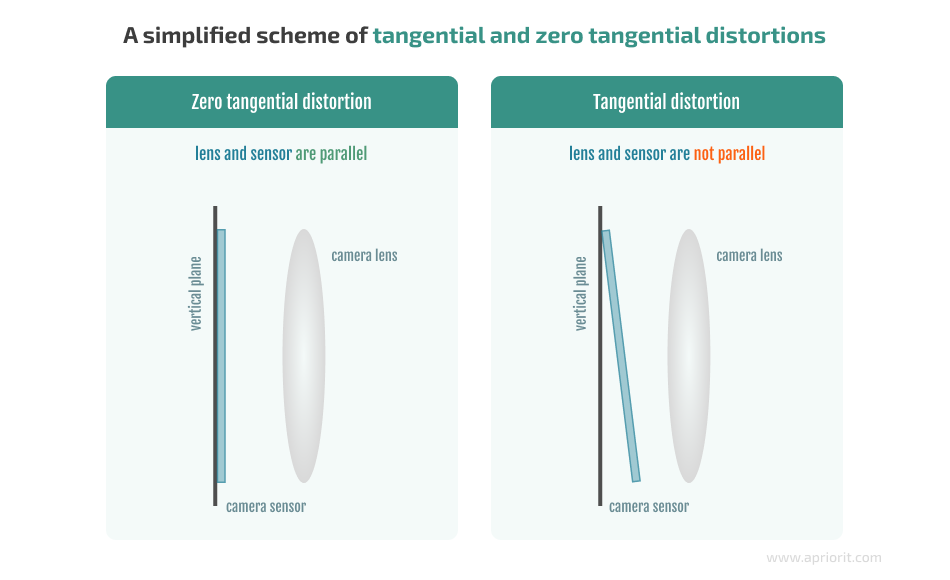
A tangential distortion occurs when an optical sensor is placed angle-wise to an optical lens.
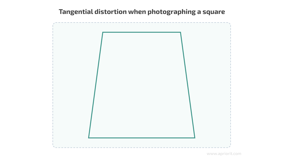
Here’s an example of how tangential distortion works when taking a photo of a square object:
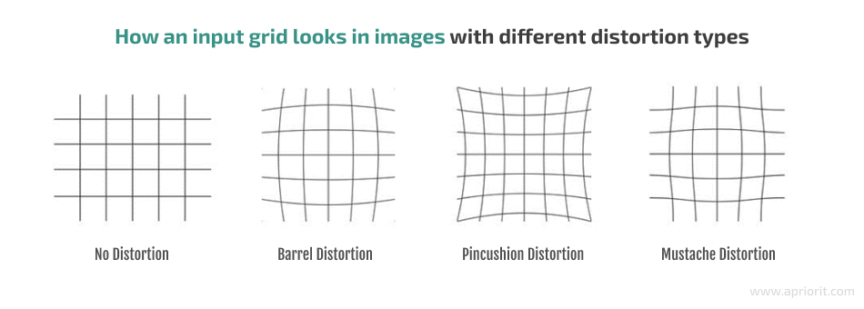
Radial distortion refers to the curvature of lines either from the center of the image to its edges or vice versa. There are three types of radial distortions:
- Barrel distortion occurs when image magnification decreases with distance from the optical axis.
- Pincushion distortion occurs when image magnification increases with distance from the optical axis.
- Mustache distortion (also called waveform distortion) occurs much more rarely than the two previous types and is essentially a mixture of them. A mustache distortion starts out as barrel distortion close to the image center and gradually turns into pincushion distortion towards the image periphery.
The type of radial distortion depends on the type and form of the lens – the more curved the lens, the more curved the lines in the final image. Let’s compare what an input grid looks like without distortion compared to when it’s photographed with lenses that cause different types of radial distortion:
With that in mind, let’s discuss how you can get rid of image distortions.
How to fix image distortions
Some modern cameras have advanced lens systems designed to minimize distortion in the final images; however, they can’t fully eliminate them. Less advanced cameras offer information about what changes need to be introduced to get rid of distortions.
And the simplest cameras, which are often used for developing custom devices, have neither of these features. To fix distortions, you first need to determine the necessary changes based on practical experiments with sensors.
Simple sensors are widespread, as they are cheap to mass produce. Even a slight difference in the design of one sensor can significantly increase the price of the entire batch.
What can you do if your camera lenses produce image distortions?
You can fix distortions using a programming method once an image has been taken. This way, you can create an algorithm for a specific camera and use this algorithm to automatically fix distortions on all images taken with the camera.
To create algorithms that can detect and fix image distortions, you can use tools such as:
- OpenCV. An open-source computer vision and machine learning software library that has more than 2,500 optimized algorithms. You can use these algorithms to stitch images, detect and recognize faces, identify objects, track moving objects, extract 3D models of objects, etc. The OpenCV library provides a common infrastructure for computer vision solutions and helps accelerate the use of machine perception in commercial products.
- AprilTag. A visual fiducial system that can be used for different tasks including augmented reality, robotics, and camera calibration. The AprilTag library is designed to be easily included in other applications, as well as to be ported to embedded devices.
- Computer Vision Toolbox. A commercial toolset that provides algorithms, functions, and applications for designing and testing computer vision, 3D vision, and video processing systems. It also allows you to automate calibration workflows for single-lens, stereo, and fisheye cameras.
- ShiftN. Automatic lens distortion correction software that works especially well for architectural images. First, ShiftN searches for straight lines and edges in the image and considers those which are sufficiently vertical to be likely architectural elements. Then, the software runs an optimization process that attempts to determine perspective, correcting the image so the lines are made parallel.
In this article, we show a practical example of determining and fixing image distortions using OpenCV, as this library has rich functionality for image processing and is free to use. Also, we have lots of experience working with it.
Read also
Artificial Intelligence for Image Processing: Methods, Techniques, and Tools
Explore how you can leverage AI technologies for your innovative product. We discuss how to use modern AI-powered image processing, from facial recognition in authentication systems to automated photo restoration and synthetic image generation.
How to identify and fix image distortions using the OpenCV library
OpenCV is a great tool for fixing image distortions. This library offers wide functionality for correcting images and calibrating camera sensors. It supports various camera models and covers different methods for finding distortion coefficients and fixing distortions. But first, you need to know how to identify image distortions using OpenCV.
By default, OpenCV uses the pinhole camera model. A calibration method determines the mockup for calibration and the markers that will be used on the mockup. The camera model determines the algorithm for calculating the camera matrix and the number of distortion coefficients to be used. Let’s define these terms:
- A camera matrix is a mathematical model for mapping points from a three-dimensional scene to a two-dimensional image, which is used when fixing camera distortions using distortion coefficients.
- Distortion coefficients describe certain distortions in an image. The more complex distortions are, the more coefficients you might need to describe and remove them. OpenCV can calculate up to six distortion coefficients for radial distortion and up to two coefficients for tangential distortion.
Now, let’s try to determine the necessary coefficients to detect and remove image distortion using OpenCV for a particular sensor.
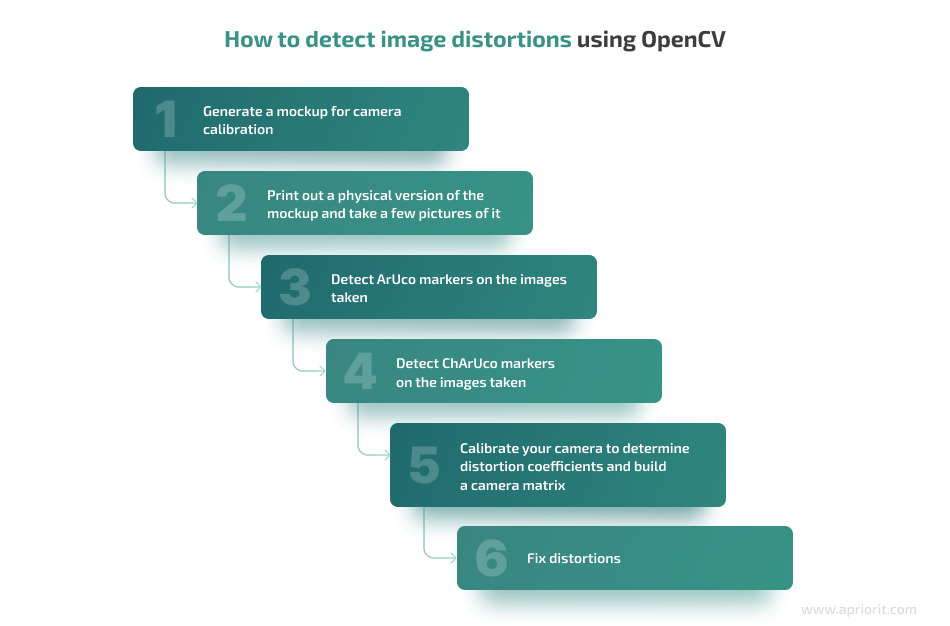
1. Generate a mockup for camera calibration
There are three types of mockups for camera calibration (also called boards):
- Chessboard
- ArUco board
- ChArUco board, which combines Chessboard and ArUco
Here’s what they look like:
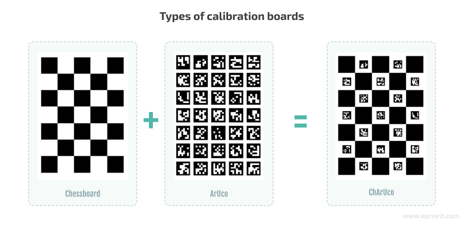
For our example, let’s use the ChArUco board because its corners are much more accurate in comparison to the marker corners.
To generate the ChArUco board in OpenCV, use the following code:
Ptr<aruco::CharucoBoard> createBoard()
{
    Ptr<aruco::Dictionary> dictionary = aruco::getPredefinedDictionary(aruco::DICT_4X4_100);
    Ptr<aruco::CharucoBoard> board = aruco::CharucoBoard::create(10, 10, 0.04f, 0.02f, dictionary);
    return board;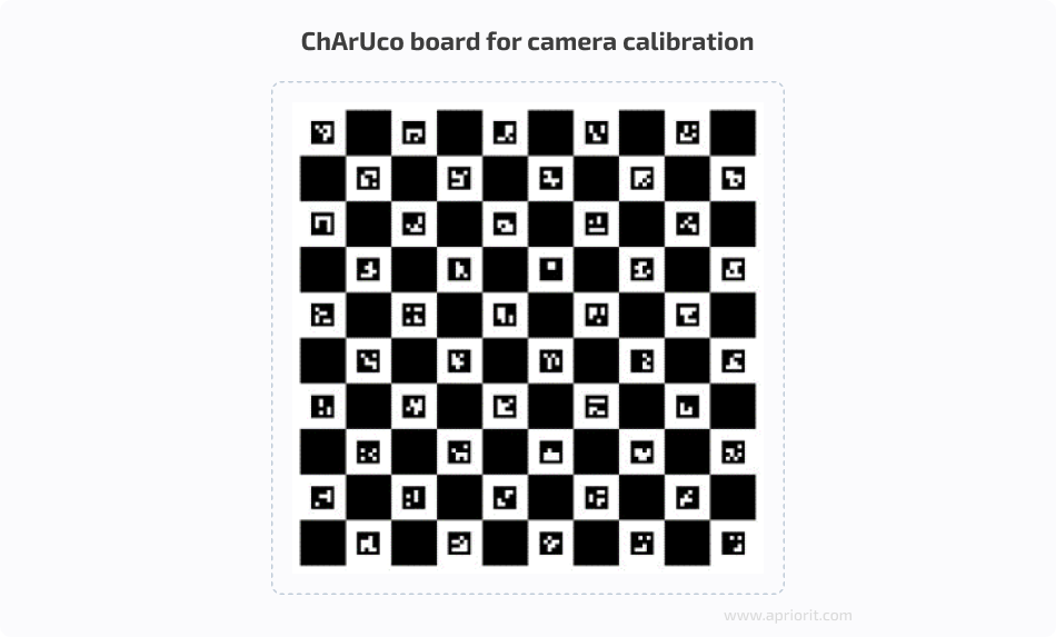
}As a result, you’ll receive the following mockup:
2. Print out a physical version of the mockup and take a few pictures of it
The more photos you take using the camera sensor you want to calibrate and the more varied the placement of the board in different images, the more accurate the coefficients you will be able to calculate.
Say you receive the following images and see that your sensor causes radial distortion:
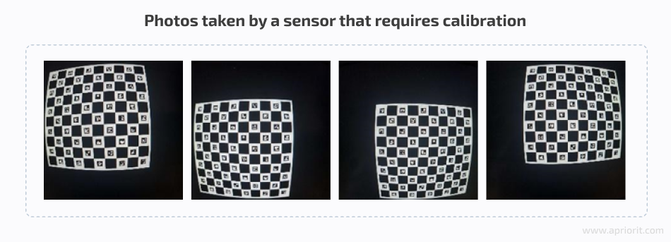
Next, upload the received images to the cv::Mat inImag variable.
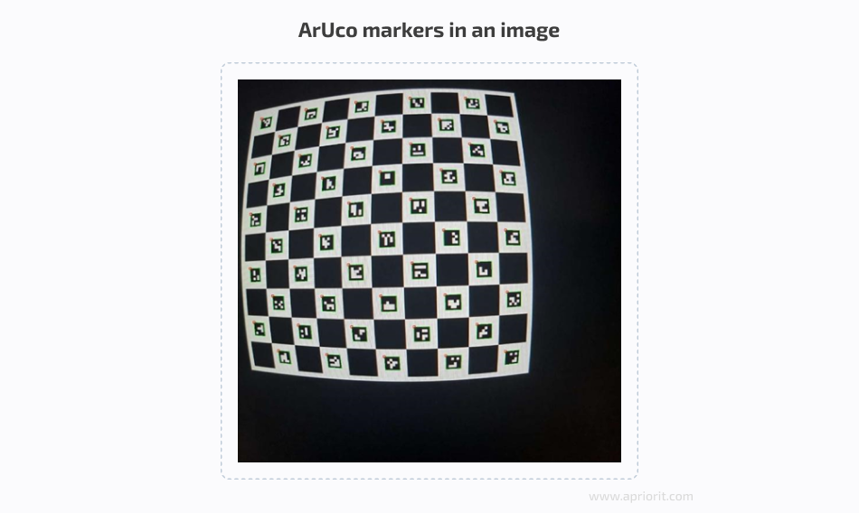
3. Detect ArUco markers in the images
To detect ArUco markers, use the following code for each image:
vector<int> ids;
vector<vector<Point2f> > corners, rejected;
aruco::detectMarkers(inImage, board->dictionary, corners, ids);As a result, the coordinates for the corners of the ArUco markers and the markers’ IDs will be recorded in the corners and ids variables. Here’s what the found markers look like in an image:
4. Detect ChArUco markers in the images
Use the detected ArUco markers to find ChArUco markers with the following code:
Mat currentCharucoCorners, currentCharucoIds;
aruco::interpolateCornersCharuco(corners, ids, image, charucoBoard, charucoCorners, charucoIds);Here’s what the detected ChArUco markers look like:
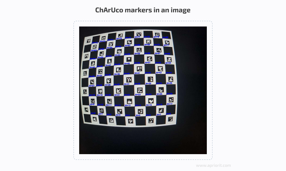
As you can see, the ChArUco markers are located in the corners between the ArUco markers (which is why we needed to find ArUco markers first).
Read also
Research on Methods for Counting the Number of People in a Video Stream Using OpenCV
Explore and compare two distinct approaches for object recognition to help you make informed decisions for your projects involving AI and machine learning.

5. Calibrate your camera to determine distortion coefficients and build a camera matrix
Once you’ve found the edges and IDs of ChArUco markers, you can start calibrating your camera:
repError = aruco::calibrateCameraCharuco(allCharucoCorners, allCharucoIds, charucoboard, imgSize, cameraMatrix, distCoeffs, rvecs, tvecs, calibrationFlags);Once you run the code above, you’ll get:
- A filled-out image matrix (
cameraMatrix) - Distortion coefficients (
distCoeffs) - A rotation vector (
rvecs) - A translation vector (
tvecs)
Now that you know distortion coefficients, you can start making your images distortion-free.
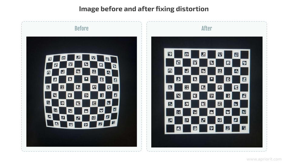
6. Fix distortion
To fix radial distortion in OpenCV, you’ll only need an image matrix and distortion coefficients:
undistort(inputImage, outputImage, cameraMatrix, distCoeffs);The undistort function fixes image distortion (inputImage) using the coefficients (cameraMatrix and distCoeffs) found during calibration. The final image is recorded in outputImage.
The undistort function, like all others mentioned above, uses the pinhole camera model by default. For other camera models, OpenCV has similar functions for identifying markers in images, correcting images, and removing distortions. When using other camera models, the number and format of a matrix that contains distortion coefficients can vary. Therefore, you shouldn’t use functions for different camera models together, as it will lead to errors in OpenCV’s functioning.
The distortion coefficients you detect will be correct for all images taken using the sensor you have calibrated for, and not only for those images used for calibration. This allows you to calibrate your camera once and then use the coefficients identified for all images taken afterwards.
Here’s an example of what an image looks like before and after fixing image distortion:
If you are dealing with especially complex image distortions, you might want to try an alternative, more accurate way to find ChArUco markers on an image:
- Find ArUco markers
- Prepare ArUco markers for camera calibration
- Calibrate your camera to get distortion coefficients and an image matrix
- Use the received coefficients and matrix to interpolate ChArUco markers
To ensure the interpolation of ChArUco markers, use the following code:
aruco::interpolateCornersCharuco(corners, ids, image, charucoBoard, charucoCorners, charucoIds, cameraMatrix, distCoeffs);This is much more accurate in cases when image distortions are complex. It allows you to significantly improve the accuracy of marker detection, but it takes much more time.
You can evaluate the accuracy of marker detection using the reprojection error value, which you can see after calling the aruco::calibrateCameraCharuco function. When calibrating a camera, it’s best to use images whose reprojection error value doesn’t exceed a certain limit. You can decide what an acceptable error limit is for your algorithm. Usually, it’s a value between 1 and 3.
If the reprojection error value exceeds your limit, you can’t use such an image for camera calibration. And if you end up excluding too many images for such a reason, consider finding markers using the second approach.
You can find the full code of the example used in this article on the Apriorit GitHub page.
Note: There are more ways to calibrate a sensor and fix distortions than those we’ve described in this article. You can also use:
- Other features offered by OpenCV. For example, you can try ArUco calibration or configure settings for camera models such as fisheye and omnidir.
- Alternative tools such as AprilTag or Computer Vision Toolbox.
There’s no silver bullet that works perfectly for every sensor. To choose the most suitable way to calibrate a camera, take into account the specifics of your particular sensor and the configuration and form of your lens.
Related project
Building an AI-based Healthcare Solution
Explore our success story in developing an advanced AI-based system for tracking and measuring ovarian follicles in ultrasound images. Our solution has improved the overall process, saving doctors valuable time and improving patient care. new capabilities to their platform and needed quality support for existing features.
Conclusion
OpenCV is a powerful tool for image correction, and in this article, we only tackled a small part of its functionality. In general, OpenCV fits the majority of cases and allows you to significantly improve the geometry and quality of an image without using complex lenses and sensors.
At Apriorit, we have professional development teams who are ready to help you deliver robust software and assist with any questions regarding AI, ML, AR, and computer vision. Our developers also have experience handling image distortions in AR projects for stitching multiple images into a flawless and unified view.
Enhance your software’s performance and security with AI
Collaborate with our expert team to harness the power of AI while mitigating potential security risks!
Have a question?
Ask our expert!
R&D Delivery Manager